TCS3200 Color Sensor Module – High-Resolution Digital RGB Light Recognition breakout
The TCS3200 Color Sensor module is an incredibly precise, high-performance, and programmable electronic optical identifier deployed extensively across India for automated industrial color sorting conveyor loops, dynamic surface scanner grids, print matching systems, and sound-reactive robotics arrays. Built around an advanced silicon light-to-frequency converter IC chip, the TCS3200 Color Sensor translates ambient primary color spectrum intensities into clean, square-wave digital output streams. This digital conversion allows microcontrollers to easily read relative values for Red, Green, Blue, and Clear light profiles without consuming heavy software processing cycles.
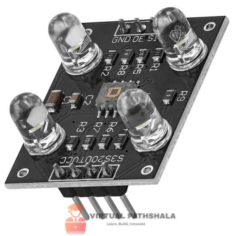
This premium listing features the highly stable black PCB breakout configuration available at VirtualPathshala. The mainboard mounts an integrated matrix array consisting of 64 discrete photodiode units flanked by four bright, clear-lens white SMD illumination LEDs. This built-in lighting ring floods target materials with uniform light, eliminating false tracking values caused by changing room shadows. Build a full-scale automated object sorter node by pairing this optical tracker link with our massive inventory of Miniature Actuator Servos and highly stable Arduino Development Boards.
Why Choose the TCS3200 Color Sensor Module Over Basic Phototransistors?
Standard light-dependent resistors (LDRs) and basic phototransistors measure only raw light intensity—they are completely blind to actual color wavelengths. The TCS3200 Color Sensor eliminates this limitation entirely by using a specialized internal grid matrix. By electronically multiplexing internal filters across its photodiode array using simple digital logic pins, it isolates specific primary light wave ranges sequentially. The output is a clean, square-wave pulse whose frequency matches the target color’s strength, giving your microcontrollers a highly precise, noise-free way to calculate absolute RGB color profiles.
Key Features of the TCS3200 Color Sensor Module
1. Sophisticated 64-Element Photodiode Matrix Architecture
The internal core of the TCS3200 Color Sensor is partitioned into four distinct photodiode filter groups to maximize scanning accuracy: 16 photodiodes feature Red-selective filters, 16 use Green-selective filters, 16 use Blue-selective filters, and the remaining 16 are left completely clear without filters. This zoning structure balances states perfectly to capture highly accurate ambient light data.
2. Built-In Multi-LED Field Illumination Ring
The module lowers integration friction inside dark project enclosures by mounting 4 bright, clear-lens white LEDs directly on the corners of the board. This lighting configuration forms a localized, highly uniform light field over your target materials, making color detection highly accurate whether operating in total darkness or uneven ambient room shadows.
3. Programmable Frequency Output Scaling (S0 & S1 Pins)
The TCS3200 Color Sensor features two dedicated frequency-scaling control input pins (**S0** and **S1**). By toggling these pins HIGH or LOW inside your sketch, you can adjust the output square-wave frequency limits to 100%, 20%, or 2% scaling, matching the pulse-counting limits of slower microcontrollers or fast digital signal processors seamlessly.
4. Universal 2.7V to 5.5V Dual Logic Voltage Layout
Equipped with an onboard low-power CMOS control core, this optical breakout syncs flawlessly with the data channels of all dominant hardware development ecosystems without requiring active external level shifter breakout chips:
- ✅ Arduino Uno / Nano / Mega boards – Direct 5V power connection utilizing native pulse-in timing pins
- ✅ ESP32 & ESP8266 NodeMCU systems – Direct 3.3V power rails for cloud-connected WiFi asset management
- ✅ Raspberry Pi Single-Board Units – Clean data tracking via standard Python GPIO hardware pulse counter logs
5. High-Speed Digital Frequency Communication Protocol
Because the TCS3200 Color Sensor module outputs a square-wave signal with a 50% duty cycle whose frequency is directly proportional to light intensity, it bypasses noisy analog processing paths completely. This digital signal can travel across longer connecting wires to your host microcontroller without suffer from signal degradation or electrical noise.
TCS3200 Color Sensor Module – Full Technical Specifications
| System Core Matrix Component |
Technical Specification Parameters |
| Electrical Power & Logic |
|
| System Working Voltage Range |
2.7V to 5.5V DC Regulated Input Rail (VCC Pin) |
| Active Operating Current Draw |
~1.4 mA typical (LEDs off) | ~25 mA peak (White LEDs active) |
| Output Signal Format Type |
Digital Square-Wave Pulse (50% Duty Cycle, Frequency scales with light) |
| Output Frequency Scaling Range |
Programmable options: 2 kHz, 100 kHz, 500 kHz (via S0/S1 Pins) |
| Digital Filter Selection Control |
2-Pin Logical Address Mapping Matrix (S2 & S3 Pins) |
| Onboard Illumination Light Source |
4× High-Bright Clear-Lens White SMD LEDs (Controlled via OE/LED Pin) |
| Sensing Core Performance |
|
| Core Detector Chipset Model |
TAOS TCS3200 Light-to-Frequency Converter IC |
| Photodiode Array Composition |
64 Filters total (16× Red, 16× Green, 16× Blue, 16× Clear) |
| Absolute Distance Testing Range |
Best results achieved between 10 mm to 20 mm gap distance |
| Non-Linearity Vector Limit |
0.2% typical value at 100 kHz threshold output |
| Temperature Coefficient Drift |
$\pm 200 \text{ ppm/}^\circ\text{C}$ structural baseline bounds |
| Physical Setup Measurements |
|
| Connecting Pin Header Array |
Dual Row 10-Pin Header Layout Split across opposite edges |
| Standard Pin Interface Space Pitch |
2.54 mm Breadboard-Friendly Holes |
| Overall Module PCB Board Size |
31.5 × 24.2 × 18.5 mm Dimensional Frame |
| Net Sensor Kit Dry Weight |
4.2 Grams Assembled Weight Profile |
What Is Safely Included inside the Package
- ✅ 1× TCS3200 Color Sensor Module with 4 Integrated White LEDs (Pre-Assembled)
Frequently Asked Questions – TCS3200 Color Sensor Module
What is the exact pin configuration map required to drive the TCS3200 module?
The module breaks its signal pins down into power lines (**VCC** and **GND**), frequency control inputs (**S0** and **S1**), color filter select lines (**S2** and **S3**), an active-low Output Enable line (**OE**), and the master **OUT** pin. Connect the OUT pin directly to a hardware interrupt or timer pin on your Arduino (such as Digital Pin 5) to let the microcontroller count incoming signal pulses accurately.
How do I cycle between individual Red, Green, and Blue scanning modes in my code?
You can select which color filter the **TCS3200 Color Sensor** reads by setting control pins **S2** and **S3** HIGH or LOW in your code loop. Setting both S2 and S3 LOW configures the sensor to read Red light. Setting S2 LOW and S3 HIGH switches it to Blue light, while setting S2 HIGH and S3 HIGH sets it to read Green light profiles. Read each channel sequentially to build a complete RGB profile.
Why are my sensor color readings drifting or shifting erratically?
Because the module relies on optical light absorption curves, external ambient shifts—like a changing room light, a passing shadow, or sunlight coming through a window—will alter the output frequency values. For rock-solid tracking stability, construct a small matte-black plastic shield or 3D-printed shroud around the sensor face. This keeps external room light out, ensuring the sensor reads only the light bouncing off your target material.
Order Your TCS3200 Color Sensor Module Online Today
Build precise automated candy-sorting robots, add industrial color-matching tracking arrays to your factory machinery setups, or engineer smart interactive exhibits with ease. Our high-yield **TCS3200 Color Sensor** is supplied across all Indian states with quick, dependable domestic shipping networks from VirtualPathshala. For official hardware data books, sample Arduino sorting sketches, and complete calibration guide files, please review the Official Component101 Electronics Engineering Reference Portal.






Reviews
Clear filtersThere are no reviews yet.